Step 1: Plan and Test Your Circuit on the Breadboard (From a Single Sensor to Remote LoRa Sensors)
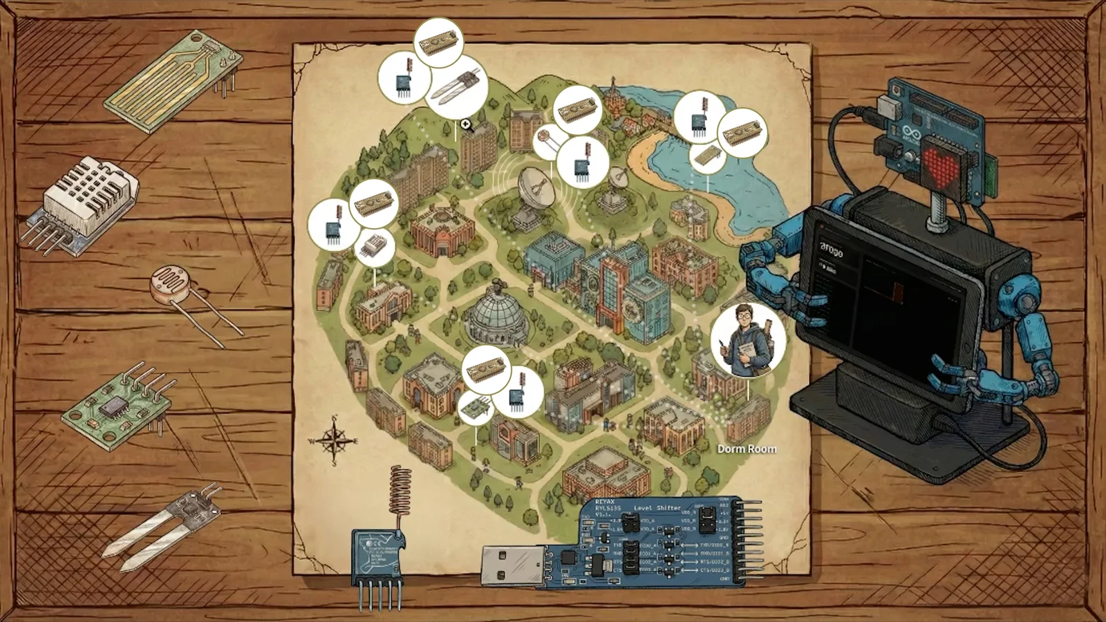
TSL2591 light sensor) with Arduino Nanos and Reyax LoRa transmitter modules around a college campus, streaming long-range telemetry back to a dorm room receiver connected via a RYLS135 USB-to-UART bridge.
Most physical AI projects start out as physical computing projects on a breadboard. Imagine you are studying science, engineering, biology, or environmental studies on a college campus and you want to run a real field research project right from your dorm room on the far end of campus.
As shown in the campus map from my LoRa video above, say you have permission to place five remote sensors miles across campus where Bluetooth and Wi-Fi cannot reach and where you cannot run a wire:
- A water level sensor down at the waterfront or beach
- A photoresistor out by the campus satellite dish
- A soil moisture sensor back in the woods
- A temperature and humidity sensor on the roof of a campus building
- A Waveshare `TSL2591` (`TSL25911`) precision light and infrared sensor under a tree
Each remote sensor is wired to a small microcontroller (like an Arduino Nano powered by a portable USB power bank) and a Reyax LoRa transceiver module acting as a transmitter. Because LoRa is a low-power, long-range wireless transceiver protocol, it can send small sensor packets (LUX:, TEMP:, SOIL:) miles through trees and buildings back to a second LoRa module in your dorm room—and because both modules are transceivers, you can even send a LoRa command back to turn a remote sensor on for 10 minutes once a day and shut it back off without Wi-Fi or Bluetooth.
Back in your dorm room (or at your home desk), the receiving LoRa module connects to a UART bridge / level shifter (`RYLS135`) and plugs directly into your laptop or a USB hub on your Arduino UNO Q. As you cover and uncover the TSL2591 light sensor—or walk away past walls and metal barriers—you see both the live lux levels (`LUX:`) and the LoRa signal strength (`RSSI:`) updating in real time on the chest screen of your desk bot or P³ workstation.
Before taking those remote LoRa sensors out into the field or mounting hardware onto a frame, you plan and test the circuit on your breadboard. (If you want to check circuit math before wiring physical parts, you can also start free in your browser with VTM Studio Lite using the circuit simulators and electronics calculators on VideotronicMaker.)
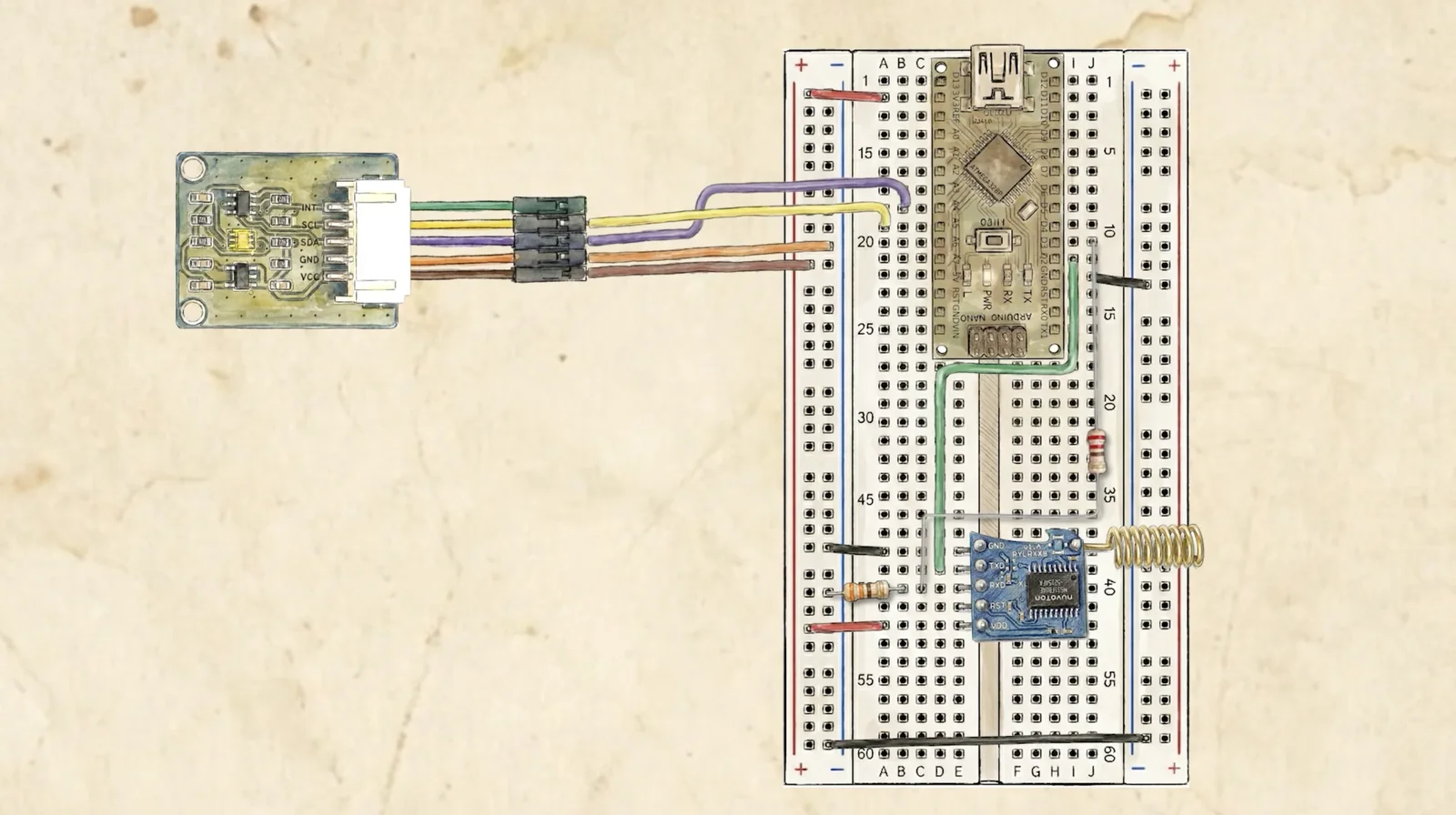
SDA to A4, SCL to A5) and a Reyax `RYLR998` LoRa transceiver powered from the 3.3 V rail (TXD to D2, with a voltage-divider resistor to ground protecting the 3.3 V LoRa RXD line).
Inside VTM Studio on your Mac, Windows PC, Linux desktop, Raspberry Pi 4B, or Arduino UNO Q, you work through five connected steps on the breadboard:
-
Plan the Breadboard in Layout Mode & Spec Mode: Draw your 2D breadboard and circuit wiring in Layout Mode (saving
.vtmlproject files or exporting layered.psd,.svg, and.pngdiagrams) while checking pinouts, schematics, and logic levels (like wiring the 3.3 V LoRa module andRYLS135UART bridge) in Spec Mode. -
Check Resistor and Voltage Divider Math in Reference Mode: Use the calculators in Reference Mode to size a voltage divider (such as dropping a 5 V Arduino Nano
D3transmit pin down to safe 3.3 V logic with a330 Ωresistor divider before it hits the LoRa module'sRXline). -
Probe Your Breadboard in Meter Mode: Flash
meter_sketch.inoto an Arduino and follow the 2-wire probe diagram in Meter Mode to measure low-voltage DC Voltage, Resistance (Ω), and Continuity on the backlit digital LCD. -
Flash Firmware in Code Mode: Open Code Mode, load one of the built-in Science Mode Examples (or your Nano +
TSL2591LoRa sketch) into the code editor, compile and flash your board over USB, and click[CONNECT TELEMETRY]. -
Watch Live Gauges and `RAW:` Serial in Science Mode: Add the matching panel (
LUX:,RSSI:,TEMP:,SOIL:,DIST:, orANGLE:) in Science Mode to watch live lux levels and LoRa signal strength update as you walk through different rooms or cover the sensor, while verifying the unparsedRAW:serial string underneath.
Step 2: Move from the Plan on Screen to Mounting on Your P³ Frame
Getting the circuit working on a flat breadboard is only half the fun. Those five steps in VTM Studio are meant to lead directly to the next step: taking your working components and mounting them onto your frame.
Note that the LoRa remote sensor project shown in Step 1 and the robotic arm images shown below are two different projects—both start as physical computing projects and grow into physical AI projects as you add vision, voice, and AI reasoning in VTM Studio. They are here as examples of the different variations you can build with your P³ builds (though you can also combine them together so a single P³ station both receives remote LoRa telemetry and drives a physical arm).
Ideally, your plan is geared toward a useful build that makes sense for Physical AI—and it does not have to be a robot. Even if you do not have a final end-product in mind yet, the good news is that this is a P³ build—which stands for Physical Prototyping Platform. That means your first builds can simply be for testing, learning, and trying things out: figuring out how to mount an arm, where to mount your sensor, or how to keep wires out of the way of moving parts.
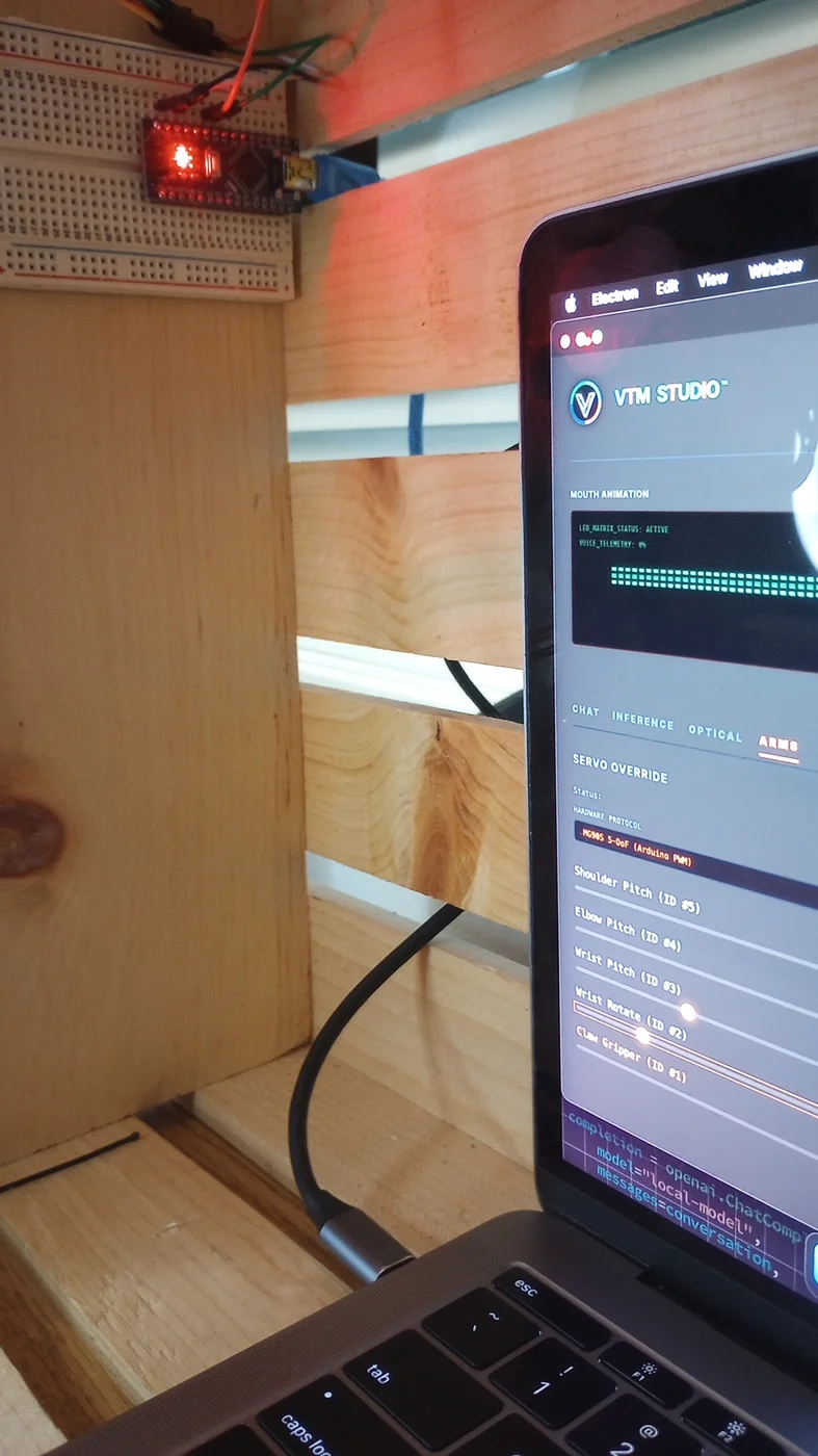
Once you start building physically, you immediately start figuring out real-world logistics—because the moment you go from a plan on paper (or a 2D layout on screen) to the actual physical build, things change. You might think an arm belongs on the outside wall of the crate, and then realize while bolting it together that mounting it underneath the top slats hanging down gives it better reach or balance. You might move a microcontroller board to an inside slat so the USB cable reaches cleanly, or add a wooden dowel strut to brace a heavy joint. Figuring out those physical logistics hands-on is what makes building a P³ fun and exciting.
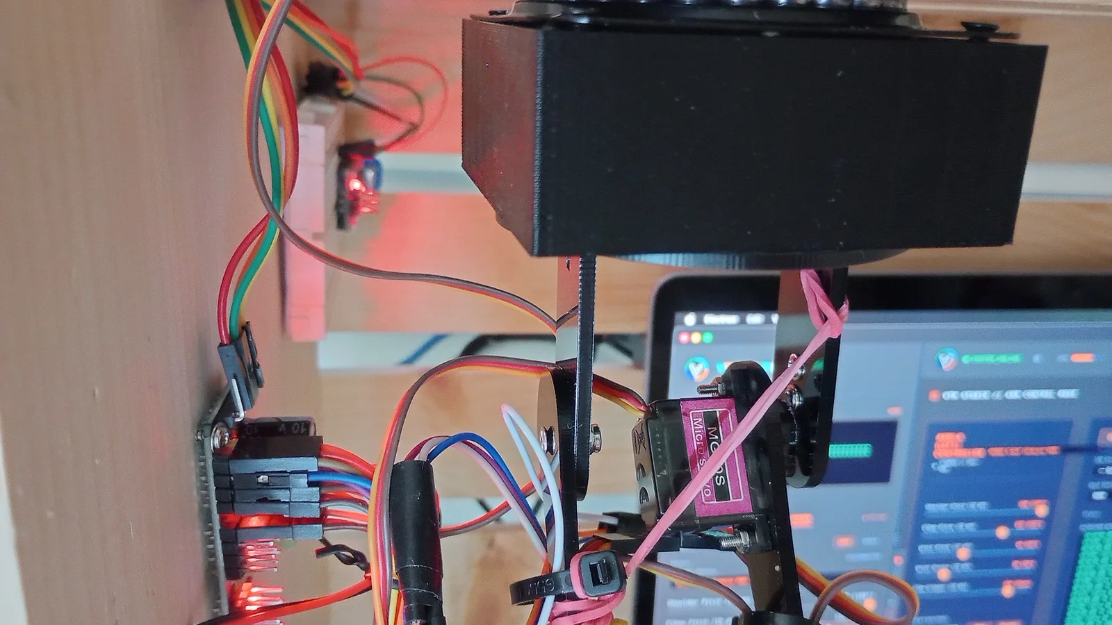
Step 3: Add AI Vision (Using Your Laptop Cam or Phone with Iriun), Voice, and Servos
With your components mounted on your frame, you turn those physical computing projects into physical AI projects inside VTM Studio—without needing to buy expensive extra accessories:
-
1. Use Your Laptop Camera or Add Your Cell Phone with Iriun in Vision Mode: You do not need to buy a dedicated USB camera to get started with AI vision. You can use the built-in webcam on your laptop, or you can add your cell phone as a camera using an app like Iriun Webcam (just as I have done on my own setup) and select it in the
CAM:menu inside Vision Mode. Using your phone lets you position the camera anywhere on your wooden crate or frame while running HSV Lock color tracking, VTM Vision object detection, or Cloud Vision. -
2. Add Voice and Mouth Animation: Use your computer's microphone and speakers for click-to-talk
faster-whispervoice input, localPiperONNX spoken audio readback, and animated mouth feedback when talking with ARC and VAS-X. -
3. Power Servos from a Separate 5 V–6 V Supply in Arm Control Mode: When you connect a servo arm to Arm Control Mode, power the servo rail from an external
5.0 V–6.0 VDC power supply (sharing a commonGNDwith your microcontroller) so moving multiple joints never drops your computer's USB voltage. -
4. Run Cloud or Local Edge AI Models in Model Forge Mode: Pair your Cloud AI keys with local models by using Model Forge Mode's 3-tab workflow to convert local Hugging Face
.safetensorsfiles to.gguf, quantize them to 4-bitQ4_K_Mor 8-bitQ8_0, and load them intollama-server.
Frequently Asked Questions
Do I need to buy a dedicated USB camera to set up a physical AI lab in VTM Studio?
No. You can use the built-in webcam on your laptop, or you can use your cell phone as a camera with an app like Iriun Webcam and select it directly from the CAM: dropdown in VTM Studio's Vision Mode.
Does a physical AI lab build have to be a robot?
No. A Physical AI project can be any purposeful physical computing build—such as a sensor and camera station, a LoRa telemetry rig, or a voice-assisted desk monitor. And because P³ stands for Physical Prototyping Platform, your first builds can simply be for testing, learning, and trying things out—like figuring out where to mount a sensor or whether to mount an arm on the side of a wooden crate or under the top slats.
How does VTM Studio guide you from a circuit plan on screen to a physical P³ build?
In VTM Studio, you first plan your 2D breadboard layout in Layout Mode, check pinouts in Spec Mode, verify resistor math in Reference Mode, test voltage and continuity in Meter Mode, and flash C++ firmware in Code Mode to watch live gauges in Science Mode. Once the circuit works on the breadboard, you mount those components onto your P³ frame—where going from a plan on paper or screen to the actual physical build helps you work out real-world logistics.